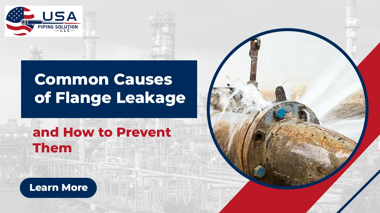
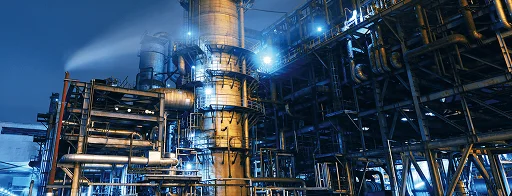
A flange gasket leak is more than just a logistical headache. It can damage the integrity of the system, worker safety, and production. The consequences are even more dire in a flange leak refinery or petrochemical environment where failure to make a seal can lead to fugitive emission violations, fire hazard, and expensive shut-downs.
This flange leak prevention guide addresses all major causes of flange leaks: flange gasket failure, leaky flange bolts, misalignment of flange faces, corrosion, vibration and thermal expansion mismatch. It ends with a combined prevention section, so you'll know next time when you ask, “why is my flange leaking?”
Browse our full range of pipe fittings and flanges to source components matched to your pressure class and service conditions.
What Makes a Flanged Joint Fail
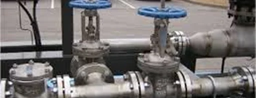
There are three components to provide pressure at a flanged joint: the flange faces, the gasket, and the bolts. If one of those components is incorrect for the service, installed improperly, or damaged during service, the sealing stress is lost in the joint and the process fluid is able to get out.
The majority offlange gasket failure causes are a result of what was done before the wrench hit the first bolt nut, material selection, face condition, and verifying alignment.
Cause 1: Flange Gasket Failure Causes
Wrong gasket material: Each process fluid has a specific gasket that should be used that is compatible with its temperature, chemistry and pressure range. A rubber gasket will harden and crack in a 400°F steam line within weeks. A fiber sheet that has been compressed will dissolve starting at the bore and moving outward in the concentrated acid. These are both well-known types of flange gasket failure.
Re-used gaskets: Gaskets that have been taken out of an older assembly and set in a new one. It is unable to be re-flown into the face serrations on reassembly and is one of the most common causes in post-leak investigations.
Wrong gasket dimensions: A too narrow gasket will cause stress to peak at the inner bore surface, and a too wide gasket will distribute bolt load below minimum seating stress required to seal.
Cause 2: Flange Bolt Torque Leak
Incorrect bolt loading drives a large share of field-reported flange gasket leaks.
Under-torqued bolts leave the gasket under-compressed. The joint weeps immediately on pressurization or develops a slow flange bolt torque leak under operating load.
Over-torqued bolts crush the gasket material past the bolt circle, creating thin spots that cannot carry pressure. This is gasket compression failure triggered by excessive bolt load.
Uneven bolt tightening in a clockwise sequence over-compresses one side of the gasket while leaving the other unseated, producing flange face misalignment leak symptoms even on a correctly aligned joint.
Cause 3: Gasket Compression Failure Over Time
Gasket compression failure does not always happen at assembly. It develops during operation.
Thermal cycling and bolt relaxation: Each heat-up and cool-down cycle causes the bolts to relax through embedding relaxation. Without a re-torque after first heat-up, the gasket loses seating stress and a flange gasket leak appears weeks after a clean startup.
Creep in soft gaskets: PTFE and compressed fiber gaskets thin slowly under sustained compressive load at elevated temperature. As the gasket thins, bolt load drops and the joint eventually weeps. This is one of the most common causes of flange leakage in steam and heat exchanger circuits.
Pressure surges and water hammer: Sudden pressure spikes beyond the design rating reduce the net sealing force at the gasket face and accelerate gasket compression failure over repeated cycles.
Cause 4: Flange Face Misalignment Leak
A flange face misalignment leak occurs when the two mating faces are not parallel or concentric before bolting, and it is entirely avoidable.
Angular misalignment means one face is tilted relative to the other. Pulling the bolts tight closes the gap on one side but leaves the opposite side unseated, creating a direct leak path that re-torquing alone cannot fix.
Lateral offset introduces a permanent bending load into the joint when bolt holes are forced into alignment, distorting the sealing face and unloading one side of the gasket.
Pipe support movement in process plants causes previously correct joints to develop a flange face misalignment leak over time as rack settlement or spring hanger failure shifts pipe loads.
For guidance on flange face types and their sealing requirements, see our types of pipe flanges complete selection guide.
Cause 5: Flange Face Damage and Surface Defects
A physically damaged flange face prevents the gasket from conforming to the sealing surface, regardless of how well everything else is done.
Radial scratches from careless gasket removal create straight-line leak paths across the face. Even a shallow mark from a screwdriver is enough to cause leakage at operating pressure.
Pitting from corrosion leaves voids the gasket bridges over. Process fluid migrates through the void and the joint leaks from the bore outward.
Weld spatter and impact damage create hard high spots. The gasket seals only against those points while the rest of the face remains unloaded.
Cause 6: Corrosion and Material Incompatibility
Corrosion attacks the joint from both the process side and the external environment and is a frequent cause of flange leakage in coastal, offshore, and chemical plant settings.
Galvanic corrosion occurs when dissimilar metals are bolted together in the presence of moisture. The less noble metal corrodes rapidly, degrading both the flange body and the sealing face.
External atmospheric corrosion degrades bolt threads in marine and chemical environments until the studs snap under re-torquing loads, leaving the joint under-bolted.
Process-side attack dissolves gasket material and the flange bore from within. In sour gas and hydrogen sulfide service, a common scenario in flange leak refinery investigations, improperly specified carbon steel flanges develop sulfide stress cracking.
Cause 7: Vibration and Dynamic Loading
Vibration is a slow but reliable bolt-loosening mechanism that turns a correctly assembled joint into a chronically under-bolted one.
Each vibration cycle causes a small rotation of the bolt relative to the nut. Over thousands of cycles, the bolt loses its preload entirely. Reciprocating compressors and pumps are the most common sources of this type of flange bolt torque leak in the field. Soft gaskets also develop fatigue cracks under cyclic loading, which grow until the joint fails.
Cause 8: Thermal Expansion Mismatch
When two flanges joining components of different materials experience a temperature change, they expand at different rates. The differential movement introduces shear stress at the gasket face and reduces effective seating stress. This is a recognized cause of flange leakage in high-temperature piping where dissimilar materials meet at a joint, such as where a carbon steel spool connects to a stainless steel nozzle or an FRP component.
How to Prevent Flange Leaks
Addressing the causes of flange leakage requires action at every stage, from material procurement through ongoing maintenance.
- Gasket selection and handling: Always install a new gasket that is matched to the process fluid, design temperature, and design pressure. Never re-use a previously compressed gasket. For high-pressure carbon steel service, ASTM A105 flanges paired with spiral wound gaskets with inner rings deliver consistent, leak-free sealing. Specify RTJ or spiral wound gaskets with inner rings for high-temperature and thermally cycled services to resist creep.
- Bolt torque and tightening procedure:Use a calibrated torque wrench or a hydraulic bolt tensioner assuring correct bolt torque for each assembly. Tighten in a cross-bolt (star) manner using 3 passes of hand-tight, 50 percent and 100 percent of target torque. Retorques all bolts following initial heat-up cycle in any thermally cycled service. Periodically re-tighten torque on flanges around reciprocating equipment; use prevailing torque nuts or approved locking fasteners to prevent vibration-induced bolt loosening
- Alignment verification:Checking parallelism of mating flange faces for alignment using a gap gauge before inserting any bolt is crucial. The maximum difference in position of the bolt holes is allowed according to ASME B16.5 is ± 1.5 mm. Always correct the alignment of pipes prior to installation, and do not use bolt tension to correct flanges. Use expansion loops or flexible joints when joining materials that have different thermal expansion, upstream of the join to absorb differential expansion.
- Flange face inspection and care:Check all faces prior to assembly with a straight edge and sufficient lighting. For minor surface marks use fine grit abrasive cloth in a concentric pattern and not radially. Portable flange facing is used for deep pitting/gouging. Only plastic or bronze gasket scrapers be used to remove the gasket and never steel chisels directly on the sealing surface. Wherever there is a known problem with water hammer, install surge suppression equipment.
- Material selection for corrosion resistance: Select flange material matched to both the process fluid and the external environment. For aggressive process service, stainless steel flanges in 316L or duplex grades resist internal and external attack. For general industrial service, carbon steel flanges with protective coatings and scheduled inspection intervals control external corrosion effectively. Use insulating flange kits wherever dissimilar metals are bolted together to prevent galvanic attack.
- Documentation: Record the torque wrench calibration ID, final torque value, gasket material and lot number, and the installer name for every assembly. This record makes future flange leak troubleshooting faster and more accurate.
The Bottom Line
Flange gasket leaks rarely happen without warning. Every failure traced back to the causes of flange leakage in this guide, whether wrong gasket material, poor bolt torque, misaligned faces, surface damage, corrosion, vibration, or thermal mismatch, had a point where the right check or the right material would have stopped it. A consistent approach to specification, assembly, and inspection is how to prevent flange leaks across any industry. For flanges matched to your service conditions, explore our carbon steel flanges, stainless steel flanges, and the full pipe fittings and flanges range.
USA Piping Solutions supplies flanges and gaskets for oil and gas, refinery, and chemical plant piping systems across North America and internationally. All flanges are supplied with EN 10204 3.1 mill test reports. ASME B16.5 and B16.47 dimensional compliance is standard across carbon steel and stainless steel flange stock.
Frequently Asked Questions
What is the most common cause of a flange gasket leak in a new installation?
Incorrect bolt torque is the top cause. Under-torqued bolts leave the gasket under-compressed; over-torqued bolts crush it into gasket compression failure. Either way, the joint leaks at startup or within the first few operating hours.
Can I stop a flange gasket leak by re-tightening bolts without a full shutdown?
Re-torquing works only when the gasket is intact and the leak is from under-torqued bolts. If the gasket is crushed, cracked, or chemically degraded, adding bolt load will not fix the flange gasket leak. Full replacement is needed.
How does flange face misalignment cause a leak even when the gasket is correct?
Misaligned faces are not parallel, so bolting them together compresses the gasket unevenly. One side over-compresses while the opposite side stays unseated, leaving a direct leak path. Fixing alignment before bolting is the only solution.
How often should flanged joints in refinery service be inspected?
Hydrocarbon service flanges need a formal check at every turnaround. Joints near rotating equipment or high-temperature service need re-torquing after the first heat-up, with integrity walks covering all flanged areas each operating shift.
Our Blog List
Application Industries
 Boilers
 Heat Exchangers
 Power Plants
 Steam Piping
 Refineries
Drop us a line
We respects customer privacy and ensures absolute confidentiality of any information that is given to us.